About the project
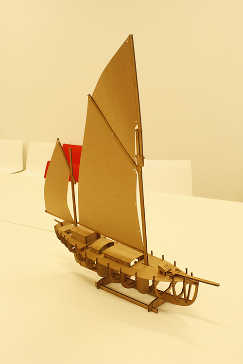
My initial ambition when joining the fab lab was to combine my understanding of traditional boat composition, with modern fabrication technologies. Translating ship loftings and lines plans into 3 dimensional forms would both be considered an important aspect to expressing such an understanding. It was this personal goal that sparked my initial motivation to create an educational model in honor of Conor O Brien designed ketch, the Ak Ilen. My envisioned goal was to create a fun and interactive way to learn about traditional boats. in the same way products like Lego Technic can explain the dynamic motions of an engine to a child. I have always felt that tactile learning provides the greatest insight, when attempting to understand complex objects.
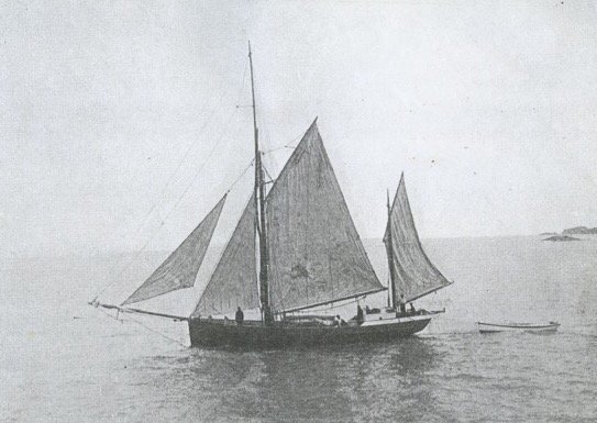 Ak Ilen under way.
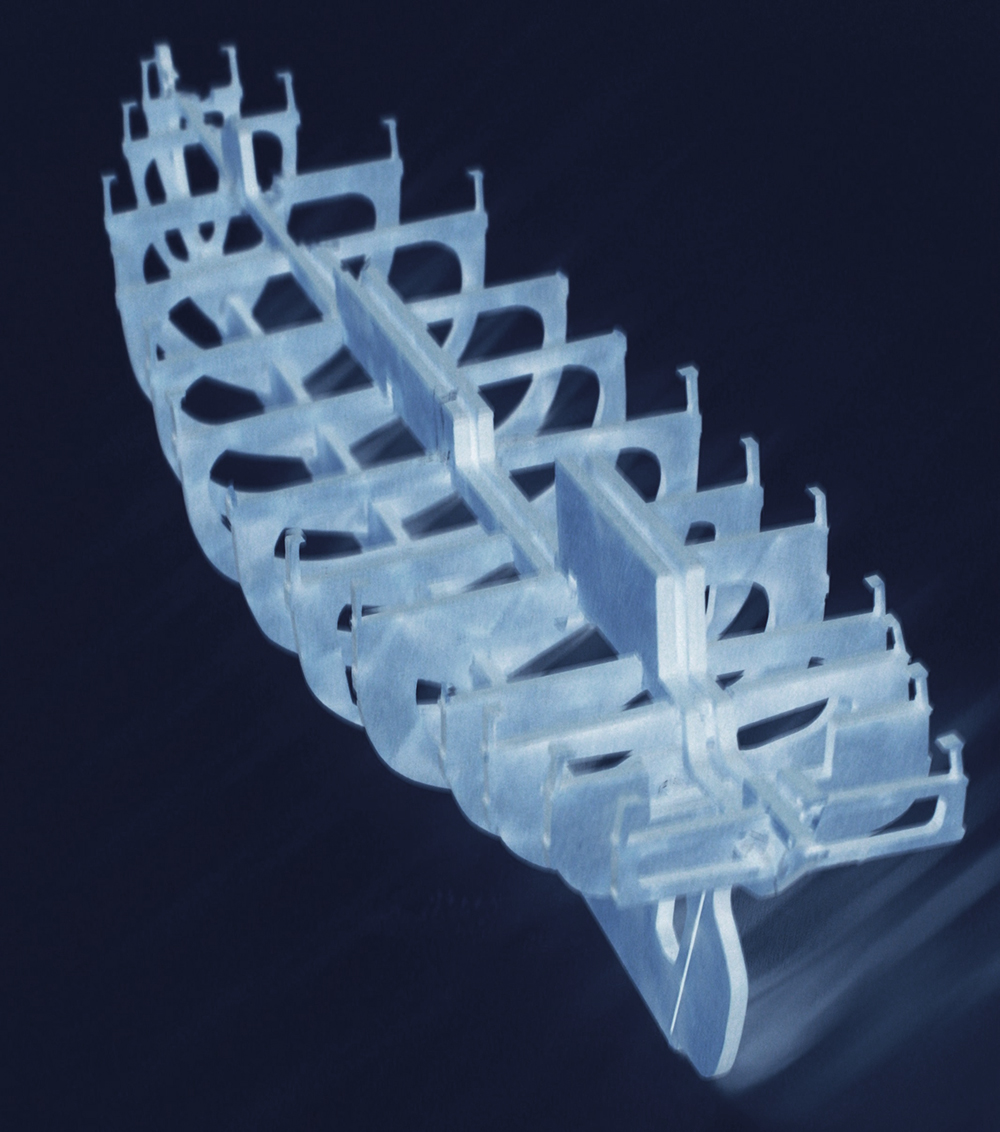
I set out to create this model by studying the lines plans made available to me. This allowed me to generate a rough plan for assembly. In my early sketches I decide to use the keel (back bone assembly) as a base to mount my station profiles at corresponding intervals. This is very similar to methods used by shipwrights to create hull forms for a ships hull. Often a full scale form is used to build upon, in the early stages of a boat build. This guarantees a hull accurately represents a ships lofting. Once I had established this general method of assembly for the finished model, I began the mammoth task at hand.
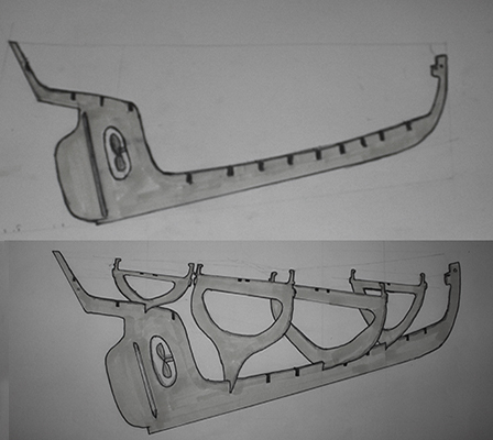 Early rendering of anticipated model assemby
My first action was gathering a selection of reference imagery. I used a lines plan and general assembly layout for the vast majority of my references material. Once these assets had been gathered I began the drafting process. I took high resolution photographs into photo-shop. I then used this software to scale both the assembly layout and lines plan to my desired size in mm. I then began selecting all the outlines to create a clipping mask containing all of the dimensional data. This mask was then used to construct an illustrator file to generate all of the individual parts.
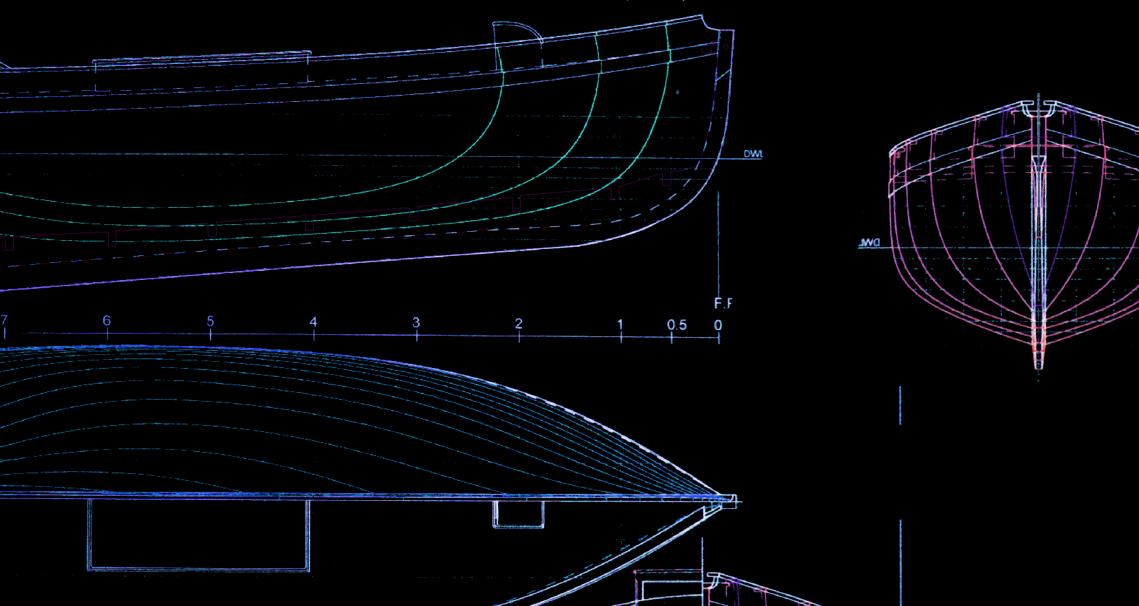 Lines mask created using assets credit to Pat Tanners drawings provided to the ak ilen school.
First draft
The first step of an arduous journey.
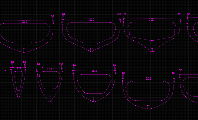
On my first attempt I scaled the model to 30cm with a slot width of 2mm. I used the front and rear projections of the boat to generate each station profile. the first outlines of each station contained minor details like the hand rails, sheer and cockpit aft. As planned the backbone would provide all relevant off sets needed for each profile location.
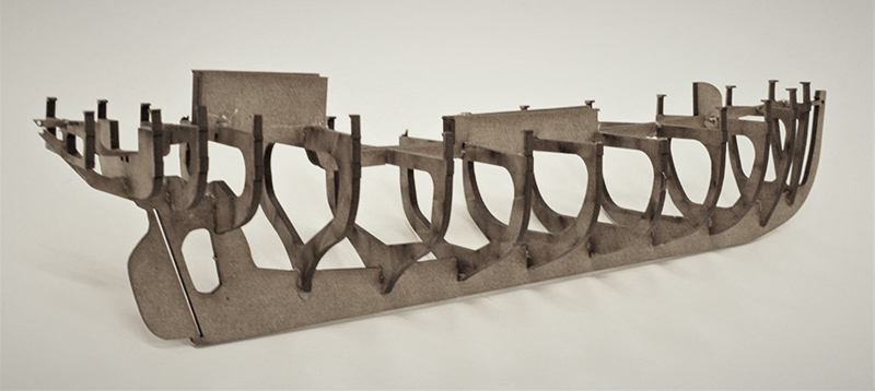
In this early rendition I also included a double deck house outline center set. I hoped this would add rigidity to the model. After a couple of weeks the model was ready for printing. I produced two cut out models and spent the weekend assembling them. Stopping along the way to take notes describing any alterations and improvements that could be made along the way.

second draft
An opertunity for alterations.
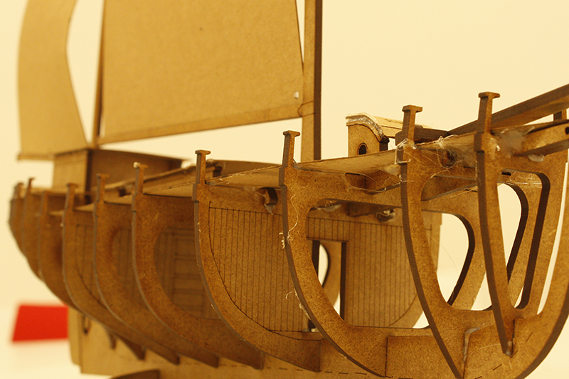 First inclusion of additional details
After a brief consultation with friend and shipwright Matthew Dirr. I then began to outline what additional details I could add, limited only by the looming deadline. I began composing my second draft of the model. my first alterations where changing the slot widths to 2.75mm to aid in the ease of assembly. This was achieved by scaling the drawing until the slots matched this dimension. I had found that my first model was quite delicate, so this size increase certainly helped in improving that element. whilst smaller alterations to the hand rails, Bulked them up a little. I later found that this made the model easier to assemble, due to the significant size and rigidity increase.
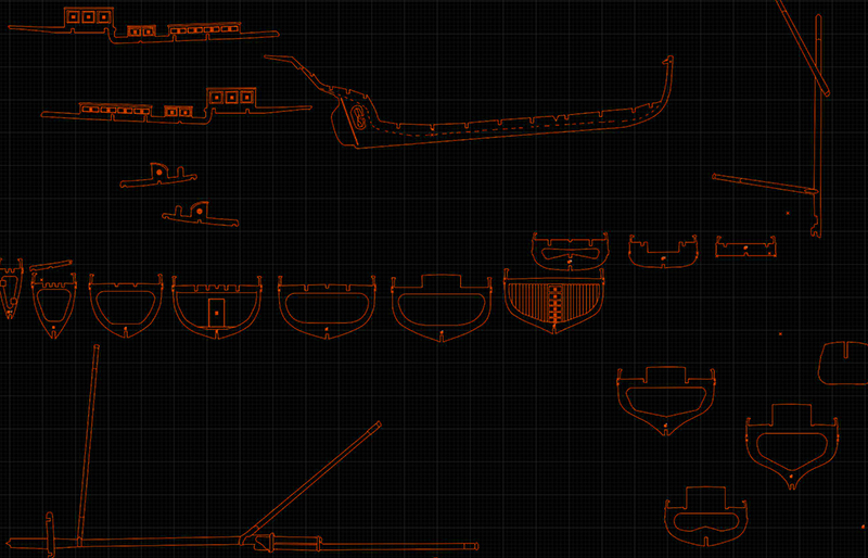
In addition to scale, I made alterations to a lot of slot locations. I also used a measurement of the deck house width, to established a true depth for the deck house profiles. this also freed up the center line for new details like the main and mizzen masts. Providing an excellent spacial representation of the deck houses, as well as adding torsional stability. I purposely interlinked the deck house profile, with the scuttle and deck beams to ensure each station remained parallel to its counterpart. Thus ensuring the forms accuracy. With the deck house profiles removed from the center line, I also began the inclusion of the rigging.
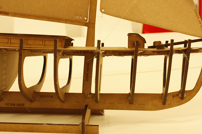
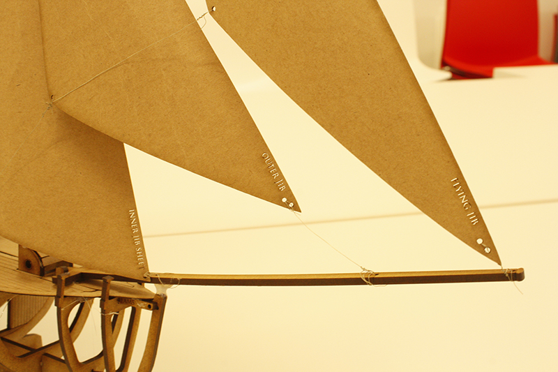
Notches where added to a station profile that coincided with the path of the mizzen mast aft. For the main mast, a key was cut into the backbone for location. Arms in the form of deck beams extruded from the mast that interlink with neighboring stations profiles, to ensure an acurate angle relative to the deck. The deck beams where needed because the mast fell in between two stations. In the process of modeling the main and mizzen as new parts into the project. Detail was added to the stations that coincided with bulkheads. This accurately represented the partitioned spaces within the hull. I feel it also provided a needed sense of scale. During the second rendition the deck house profiles where also split to accommodate the smaller width of the scuttle, forward of the main deck house. the scuttle profile pieces include the Samson posts. These will provide a mounting position for the bowsprit, another component to the rig. The bow sprit is needed for mounting of the jib sheets. An essential component to the models minimal rig.
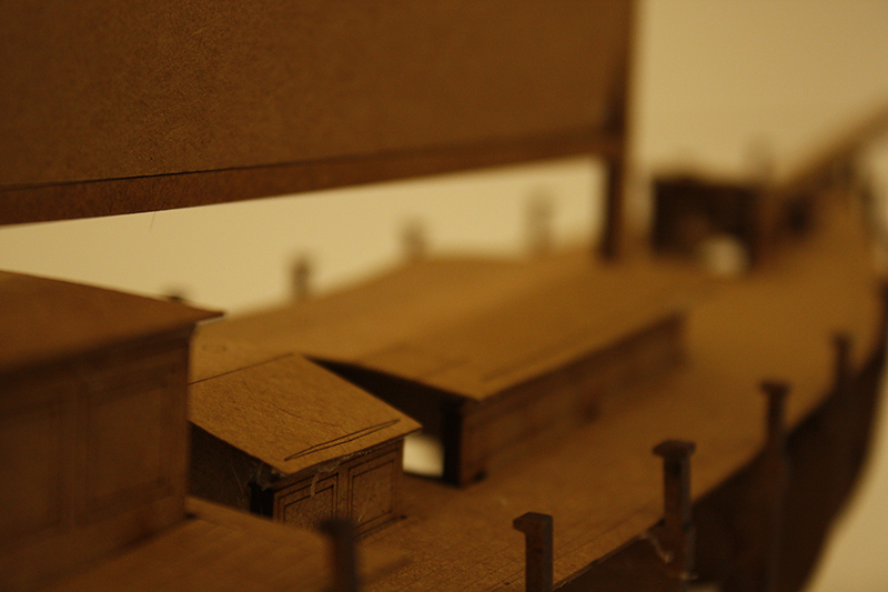
 Inclusion of deck and sails
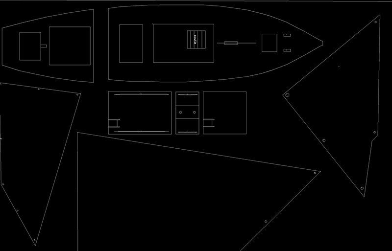
For my final improvements to this rendition. I created a new illustrator file to incorporate the fore and aft decks. Getting the deck profile to fit properly was a real challenge with multiple versions being tested, before attaining a good fit. My intention is to fabricate an envelope for final packaging out of 0.5mm brown card. With the hopes of fitting these components on the inside face for efficient use of material. Included are contour profiles of the deck house tops, as well as the sails and the ships wheel. I wanted to add the wheel housing to the cockpit for an additional scale reference.
In printing this second draft, I have eliminated most of the mistakes from the first model and added some interesting details for a sufficient depiction of the vessel. The assembly went very well and in its completion I found solace in admiring its form.

final draft
The beginning of the end.
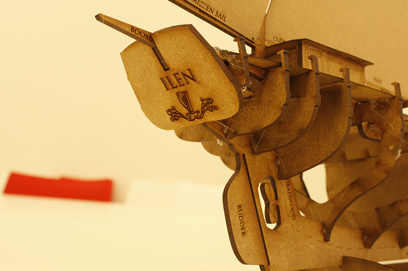
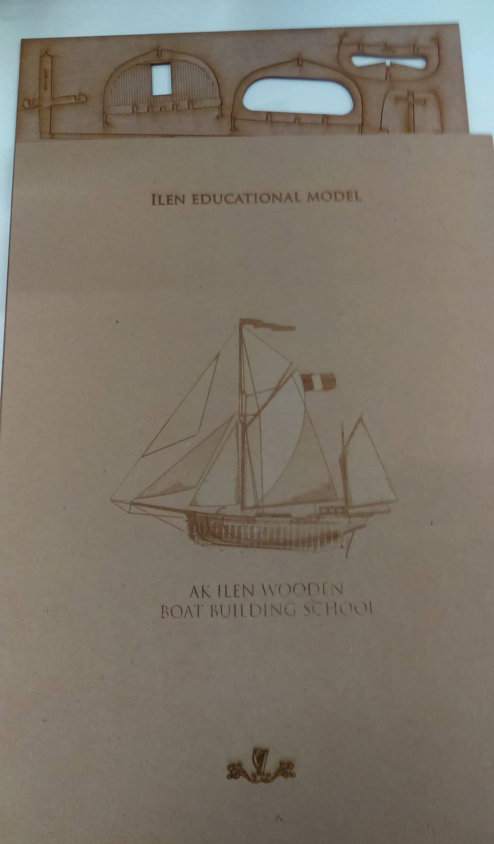
At this stage I found myself nearing the completion of the model. My final draft would include the addition of some additional detailing, to many of the models parts. I wanted to add minor details to the outline of its components and parts to aid in the visual communication of the ships composition. I also added some labels where possible in the hopes of aiding in this descriptive process.
Upon adding these finishing touches, I began taking photographs of the assembly process. Taking breaks along the way to document the models general assembly. I will use these images for generating a brief instructional page with photoshop later, Detailing this assembly process. To be used as a reference of assembly for the end user.
The final act of composing this project was to design a sleeve to contain the model. With the hopes to incorporate the card, deck and sail components into its internal face. However, Due to the sail area. This simply wast possible, and so I resorted to adding these pieces separately
In conclusion, i really enjoyed the process of generating this model from a ships lofting. I found that it helped me to develop a greater understanding of such documents and gave me a firm foundation for creating my own hull forms in the near future.